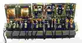
Another view of the interior of the AR-812 with the works exposed. Note the catacomb "box" in the centre with the six holes for the tube socket; each tube is type UV-199.
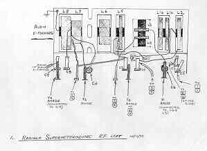
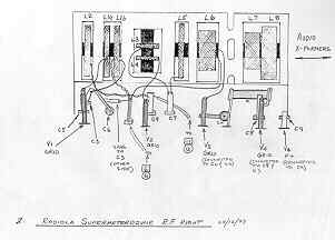
Once the wax has been melted away, you should be left with the catacomb remaining as depicted below. I followed the circuit diagram and came up with the drawings of both sides of the catacomb. Click on the pictures for a better view
Click on the image to see a larger viewThe unveiled catacomb reveals the faulty I.F.and audio interstage transformers exposed. The R.F. and I.F. transformer winding appear to be held in place with black friction tape and the remaining beeswax. Fortunately, the open I.F. transformer was traced to a lead dislodged from a binding post; I would imagine any such R.F./I.F. transformer faults will not generally require removal.
The audio transformers were later removed and disassembled. I have often had success with open audio transformer windings by disassembly, removal of the paper covering and "digging" into the windings. In this receiver, one transformer was "salvagable" but the other had numerous openings and was beyond hope.
I've been told that replacement winding coils are available through the Antique Wireless Association. However, I had the good fortune of finding a replacement through the online auction house, "ebay". The ebay lot consisted of the AR-812 front panel and chassis only and I took a chance on it. With great fortune, BOTH transformers have been tested as good. They have been successfully removed and are awaiting installation!